Ellipse command in AutoCAD
Ellipse command in AutoCAD
Two
focal points are encircled by a curve, which is known as the Ellipse.
Two
of the ellipse's axes, which specify its length and breadth, determine its
form.
The
Ellipse command on the AutoCAD display allows you to construct ellipses in
general.
By
putting the start and end points on two different axes, we may make an ellipse.
Depending
on the specification, the first and second axes of the ellipse might be classified
as either minor or major axes.
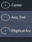
The
icon of Ellipse will look like the below image:
Move the pointer of your mouse on the Ellipse icon to view the dialogue box for Ellipse in AutoCAD. It will look like the given image:
Let's discuss each type of Ellipse in detail.
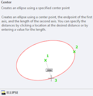
CENTRE
In this procedure, the length determines the
second axis while the centre point and terminus define the first axis. To make
such an ellipse, we can either choose a point or a distance value.
Let's use an illustration to clarify.
The actions are detailed below:
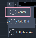
1.As seen in the figure below, click the
Ellipse symbol on the ribbon panel, and then select Center from the Ellipse's
drop-down list:
Or
On the command line or command prompt, type
el or ellipse and hit Enter.
Fill up the command line using C or copy.
Enter the key.
2.On the viewport, specify the Ellipse's
centre.
3.Declare the first axis' terminus like in the illustration below:
Either the point or the distance value can be
specified. The first axis's centre and terminus will be used to determine the
distance,such as 3.
As seen in the graphic below, we may alternatively pick the vertical axis as the initial axis:
4.Enter key.
5.Set the second axis' endpoint or distance
value. For example, 4.
6.Press Enter.
7.The Ellipse will be formed, as seen in the illustration below:
If the vertical axis was chosen as the first axis, the ellipse so formed is shown in the below image:
The three points are defined in a manner similar to above to create the ellipse.
It is displayed below:
The
first axis' position and length are determined by the points 1 and 2, whereas
the second axis' distance between its centre and terminus is determined by the
point 3.
Elliptical Arc
An elliptical arc may be made with the Elliptical Arc command.
For instance:
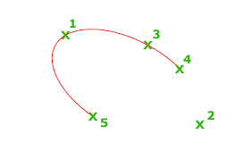
Consider the below image:
The
location and length of the first axis is specified by the points 1 and 2, while
the distance between the center and the endpoint of the second axis is
specified by the point 3.
The
fourth and fifth specified points are the start and end angles.
Let's
use an illustration to clarify:
The actions are detailed below:
1.Select Elliptical Arc from the drop-down list of the Ellipse by clicking on the Ellipse symbol on the ribbon panel as shown in the illustration below.
Or
On the command line or command prompt, type
el or ellipse and hit Enter.
On the command line or command prompt, type A
or arc and hit Enter.
2.Indicate the elliptical arc's terminus or
centre.
3.As seen below, specify the axis' endpoint:
4.As seen below, specify the other axis' endpoint:
5.Name the starting angle. 30 is an example. The following picture illustrates it:
6.Indicate the final angle. for instance,
120.
7.The created elliptical arc is shown in the
below image:
We
can also specify the Parameter angle
instead of the normal angle.
Let's
use an illustration to clarify:
Parameter
The vector equation shown below is used to generate the arc for the given angle values:
p(angle) is equal to c + a * cos(angle) + b * sin (angle)
Where,
negative major and minor axis lengths, a and
b
central point of the ellipse
Draw an Isometric Circle
If you are drawing on isometric
planes to simulate 3D, you can use ellipses to represent isometric circles
viewed from an oblique angle.
1. Click Tools menu - Drafting
Settings.
2. In the Drafting Settings dialog
box, Snap and Grid tab, under Snap Type and Style, click Isometric Snap. Click
OK.
3. Click Home tab - Draw panel - Ellipse drop-down - Axis, End.
4. Enter i (Isocircle).
5. Specify the center of the circle.
6. Specify the radius or diameter of
the circle.
Draw a True Ellipse Using
Endpoints and Distance
1. Click Home tab - Draw panel -
Ellipse drop-down - Axis, End.  Find
Find
2. Specify the first endpoint of the
first axis (1).
3. Specify the second endpoint of
the first axis (2).
4. Drag the pointing device away
from the midpoint and click to specify a distance (3) for half the length of
the second axis.
Draw an Elliptical Arc Using Start and End
Angles
1. Click Home tab - Draw panel - Ellipse drop-down - - Elliptical Arc.
2. Specify endpoints for the first
axis (1 and 2).
3. Specify a distance to define half
the length of the second axis (3).
4. Specify the start angle (4).
5. Specify the end angle (5).
The elliptical arc is drawn counterclockwise between the start point and endpoint.


Comments
Post a Comment