Posts

Showing posts from October, 2022

Attedit command in AutoCAD

  Attedit command in AutoCAD At the Command prompt, modify a block's attribute data. You may filter the properties that need to be changed based on the attribute tag, the current value, or the selected item. Be sure to adhere to these rules when setting a filter: ·        To limit what may be modified, type the precise name of a block, attribute tag, or attribute value. Since attribute values and tags are case-sensitive, capitalize the correct words. ·        If you do not wish to filter on a certain block, tag, or value, press Enter to accept the asterisk (*). ·        To select and modify empty attribute values, type a backslash (/). The following questions are shown. Edit each attribute separately? Indicates whether modifications are made locally or globally. Yes. edits each property individually. The attributes must be clear and in line with the existing UCS. With this technique, you may alter the text string as well as attributes like height and color. No.

Ellipse command in AutoCAD

Image
  Ellipse command in AutoCAD Two focal points are encircled by a curve, which is known as the Ellipse. Two of the ellipse's axes, which specify its length and breadth, determine its form. The Ellipse command on the AutoCAD display allows you to construct ellipses in general. By putting the start and end points on two different axes, we may make an ellipse. Depending on the specification, the first and second axes of the ellipse might be classified as either minor or major axes. The icon of Ellipse will look like the below image: Move the pointer of your mouse on the Ellipse icon to view the dialogue box for Ellipse in AutoCAD. It will look like the given image: It consists of the drop-down list, which includes other options such as Elliptical Arc, Center, and Axis . The list will look like the given image: Let's discuss each type of Ellipse in detail. CENTRE In this procedure, the length determines the second axis while the centre point and terminus defin

Point Command in AutoCAD

Image
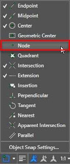
  Point Command in AutoCAD Points in AutoCAD 2D may provide excellent reference points for additional drawings. In this post, we'll demonstrate how to construct single and multiple points in AutoCAD 2D, along with the command that accomplishes this. Using the POINT or PO command in AutoCAD , you may create simple points, also known as nodes. Simply write PO, hit Enter, and then click at a position in the drawing area to produce a point, or enter the coordinates of the desired point. The point will by default show up as a single dot in the drawing area, and you may use these points as references to create your design. To modify this, activate the node option in the object snap status bar option as shown in the image below. By default, the points won't be selectable. A different point types The default point is a tiny pixel-sized dot, which works well for the majority of purposes, including creating references. However, the PTYPE command also allows you to alter t