Point Command in AutoCAD
Point
Command in AutoCAD
Points in AutoCAD 2D may provide excellent
reference points for additional drawings. In this post, we'll demonstrate how
to construct single and multiple points in AutoCAD 2D, along with the command
that accomplishes this.
Using the POINT or PO command in AutoCAD, you may
create simple points, also known as nodes.
Simply write PO, hit Enter, and then click at a
position in the drawing area to produce a point, or enter the coordinates of
the desired point.
The point will by default show up as a single dot
in the drawing area, and you may use these points as references to create your
design.
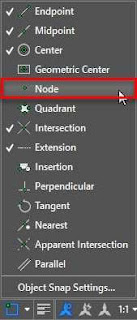
To modify this, activate the node option in the object snap status bar option as shown in the image below. By default, the points won't be selectable.
A different point types
The default point is a tiny pixel-sized dot,
which works well for the majority of purposes, including creating references.
However, the PTYPE command also allows you to
alter the default point style.
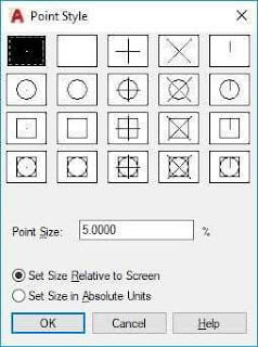
The Point Style window will pop up with a list of the possible point styles once you type PTYPE on the command line and hit Enter. From this selection of point styles, you can choose any other point style, then click OK to apply it.
If you switch the point style after creating
points with a different point style, all of those points on the drawing area
will likewise switch to the new point style.
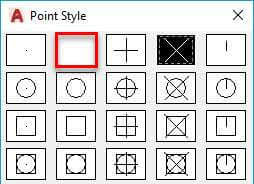
Simply choose the second point in the Point Style
window, which is shown as a blank box in the image below, if you need to hide
points from the drawing area or if you do not want to plot the points.
The points can alternatively be placed on a no
plot layer, or you can utilize AutoCAD's conceal or isolate tools.
You may also use the PDMODE command to modify the
point type straight from the command line.
PDMODE's default value of 0 creates a point that
is the size of a pixel. As demonstrated in the figure below, you may adjust
this to any value between 0 and 4 to alter the point type.
In this situation, setting the value to 1 will
make the point invisible in the drawing area.
All of the PDMODE point types and their related
values are listed on this AKN page.
Varying the point size
The point size will by default depend on the size
of the screen and using the zoom command will not alter this.
If zooming in and out affects the point size, use
the RE command to renew the drawing objects to restore the point size to the
current drawing area.
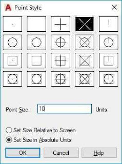
However, you may alter this parameter to create
points with an absolute size that adjusts in size as you zoom in or out.
Once you click OK, you'll see that your points'
sizes will remain consistent regardless of whether you zoom in, out, or renew
your design.
How Do I Create Multiple Points and
Points in AutoCAD 2D?
The point must first be created in AutoCAD before
using the 'Multiple Points' option from the 'Draw' menu, as shown by the red
arrow.
You only need to click where you want to
construct your points after typing the "Multiple Point" instructions.
The AutoCAD "Multiple Points" command generates a large number of
points, as you can see above.
When finished constructing many points, just use
the "Esc" key on your computer to leave AutoCAD's "Multiple
Points" command.
Conclusion
Mechanical Drawing Using AutoCAD® 2017: Learn
AutoCAD!
Click on the provided link or the "Shop
Now" button to check out the book that Mechanical land has selected for
learning AutoCAD 2D® at an engineering level from Amazon!
Don't forget to post any comments or inquiries
you may have concerning AutoCAD's "Multiple Point" commands below!
To alter the point style, do the
following:
1) Select "Point style" from the
drop-down menu in the "Utility" panel. The 'Home' tab contains the
utilities panel.
2) You may also type "PTSTYLE" in the
command bar and hit Enter. There will be one open conversation box.
3) Based on your needs, choose the appropriate
point style from it.
4) Select the "Point size" and then
click "Ok."
5) The point style is modified.


Comments
Post a Comment